Dossier Océan et énergie - Énergie Thermique des Mers
Sommaire IOA News Letters
F.P.S.O. TECHNOLOGY APPLIED TO O.T.E.C.
Martin G. Brown,
Senior
Naval Architect,
Mathon Engineering/Noble Denton Europe
Ltd.
Abstract
 The offshore oil and gas industries are
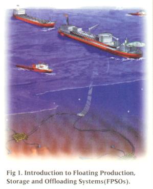
currently making increased use of mono-hull based Floating Production, Storage
and Offloading (F.P.S.O.) systems (See Fig. 1.0). Much of the experience gained
from the development of these systems, particularly for deep water sites, is
directly applicable to floating OTEC systems.
The offshore oil and gas industries are
currently making increased use of mono-hull based Floating Production, Storage
and Offloading (F.P.S.O.) systems (See Fig. 1.0). Much of the experience gained
from the development of these systems, particularly for deep water sites, is
directly applicable to floating OTEC systems.
This paper reviews the most applicable world wide FPSO developments. This survey shows how deep water technology has advanced and how costs have fallen. Drawing from this data a conceptual mono-hull based floating OTEC system has been developed. To minimize capital expenditure the system is based upon the conversion of an existing hull.
As well as a moored system positioned fairly close to land, a deep water grazing system is also suggested. For this untethered system alternative means are proposed for controlling the vessel and transporting the produced energy and fresh water back to shore. In addition, other uses of the free floating system ranging from a Deep Ocean Research Station to a floating leisure/cruise complex are also considered.
A preliminary investment appraisal is undertaken for each of the proposed designs. This identifies how close to commercial feasibility the ideas are and also identifies areas of technical risk. Finally a forecast is made of how future developments could lead to successful commercial development.
Introduction
The majority of Ocean Thermal Energy Conversion (OTEC) research and
development expenditure was undertaken in the later half of the 1970s and early
1980s.
 This work and the basics of OTEC are well summarized in ¡§OTEC -
Historical Highlights, Status and Forecast,¡¨
(Dugger et al, 1983). A major
technological change since this period has been the development and maturity of
floating production systems for the exploitation of offshore oil and gas
reserves. The developments associated with these systems are particularly
relevant for large scale floating OTEC systems.
This work and the basics of OTEC are well summarized in ¡§OTEC -
Historical Highlights, Status and Forecast,¡¨
(Dugger et al, 1983). A major
technological change since this period has been the development and maturity of
floating production systems for the exploitation of offshore oil and gas
reserves. The developments associated with these systems are particularly
relevant for large scale floating OTEC systems.
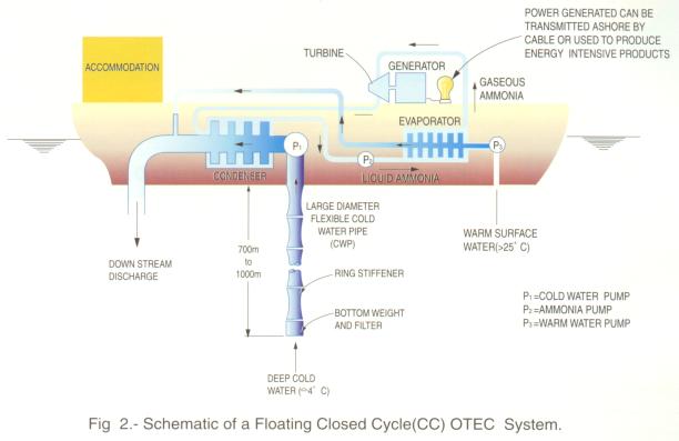
Although OTEC systems need to obtain further long term operational experience at a 1 to 10 MW scale, the intrinsic simplicity of the technology (See Fig. 2.0) is such that scaling up to 100 or more megawatts is a relatively straightforward engineering task. Hence there is a need to undertake design activity for large scale floating systems at the same time as small scale land based developments. Thus the technology will be available to move quickly if/when oil prices rise and concerns for the environment become even more pressing (e.g. possible confirmation of the seriousness of the green house gas effect for global warming).
It is worth noting that the combined effects of the world coming out of recession plus increasing third world industrialization are beginning to lead to the demand for oil increasing faster than supply. The inevitable consequence is that the oil price will start to rise.
In addition, rapid industrialization has also led to a desperate demand for electrical power in a number of countries which could benefit from OTEC generated electricity e.g. Indonesia, India, Malaysia, Philippine Islands, Indonesian Islands, Taiwan, Papua New Guinea, Borneo, etc.
The Development of F.P.S.O.s and their Current Technology Status
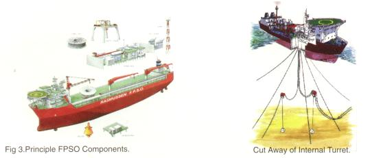
FPSO (sometimes pronounced as "fipso") is an abbreviation for Floating Production, Storage and Offloading mono-hull (e.g. tanker) vessels. The principal components consist of a new or second hand hull supporting hydro-carbon process equipment (separators, compressors, gas turbines, etc.) restrained by a weather-vaning turret mooring system with upper and lower bearings plus a fluid transfer swivel or drag chain with shuttle tanker offloading via a flexible hose at the stern of the FPSO (See Fig.3.0). One or more thrusters are sometimes provided. This is for emergencies (e.g. mooring line failure) and also to prevent vessel becoming beam on to the seas, which might very occasionally happen if there is an unusual sudden change in direction of the wind and current.
Today "mobile offshore production systems (including Semi-Submersibles, Spars and FPSOs) constitute the most rapidly expanding segment of the world-wide offshore field development market" (Crager et al., 1996). Offshore floating production began in June 1975 when Hamilton Brothers began producing in the North Sea from the Argyll field using a converted semi-submersible drilling rig "Transworld 58." Tanker based FPSOs began in 1976 when Shell installed a converted 60,000 dwt tanker at their Castellon field offshore Spain. By the end of 1997 the world operating FPSO fleet is likely to number 44 units, a remarkable 76% increase over just two years. The most significant recent departure from established practice has been the application of mono-hull FPSOs to greater water depths (See Table 1.0), combined particularly in the case of N.W. Europe with a harsh environment e.g. B.P.'s West of Shetland FPSOs "Foinaven" and "Schiehallion" respectively sited in 488 and 396m water depth.
Table 1.0 - Numbers & Geographical location of Deep Water (600 feet +) Floating Production Units
| ¡@ |
OPERATING |
CONSTRUCTION |
|
REGION |
600 + feet water depth |
600 + feet water depth |
|
South America |
9 |
6 |
|
N. W. Europe |
1 |
5 |
|
Asia/Pacific |
2 |
1 |
|
Africa |
0 |
0 |
|
Med/Middle East |
0 |
2 |
|
North America |
1 |
1 |
|
TOTAL |
13 |
15 |
Part of the reason why FPSOs have been able to be used in harsher environments has been the successful development of an internal turret design for mooring the vessel. In addition, greater operational experience has become available on the performance of key items, such as flexible risers, mooring lines and process equipment subject to vessel motions. This is extremely useful, from an OTEC perspective, since the turret represents a good point for anchoring the vessel and attaching the cold water pipe (CWP). For hulls which use a drag chain, not a swivel for fluid transfer, turrets have been designed and fabricated with a diameter up to 22m (72 feet) (Statoil's "Norne" FPSO which will operate in a water depth of 320m (1,050 feet). In addition, detachable turret moorings are also being developed for use in areas subject to typhoons and hurricanes. Being able to design a disconnectable OTEC system such that it does not have to withstand typhoon conditions can give a substantial saving on material and fabrication cost. The "Nanhai Sheng Li" FPSO survived with minor damage (eg. aerials broken) when typhoon Sally passed within 10 miles of the vessel (Offshore Int. Newsletter, Oct. 28th, 1996). The environment experienced was significantly in excess of the 100 year storm design criteria.
In addition, forthcoming and future new developments are likely to bring down dramatically costs. These include synthetic mooring ropes (aramid and polyester) and suction anchor piles. Also showing promise is Brown and Root's "BARBOX" floating production system which can support a heavy deck load with minimum pitching and rolling. The BARBOX is restrained by a spread mooring system, thus avoiding the considerable expense of a weather-vaning turret system. In addition the potential for Spar floating production systems is now being demonstrated on live projects e.g. Oryx ¡¦ s ¡§ Neptune ¡¨ Spar has already been installed and Chevron ¡¦ s ¡§ Vancouver ¡¨ Spar is under detailed design.
Now that FPSOs are proven technology they represent an attractive oil field development solution since they are re-usable, they have a residual value at the end of a project and their de-commissioning costs are low. It is interesting to forecast that as deep water FPSOs become more common and since they are re-usable, there is potential to convert one in the future to an OTEC system. Such a second hand FPSO would help to keep the capital cost of an OTEC system to a minimum.
Although a weather-vaning turret helps to minimize the environmental forces to which a FPSO is exposed, turrets, with high quality machined bearings, are expensive to build. In benign tropical areas it may be possible to get away without a turret system and instead use a spread mooring system. Such systems have been used off the African coast on J. Ray McDermott's "Jamestown" FPSO, Oceaneering's "Zafiro Producer" or Elf's "N'Kossa" project. The "Jamestown" (40,000dwt) is interesting since this is a very elderly vessel (1957 built) where as the 1973 built "Zafiro Producer" is significant due to its large 268,000dwt size.
For oil and gas floating production systems concrete is starting to emerge as an alternative construction material compared to steel, e.g. Norsk Hydro's Troll "A" concrete semi-sub (209,850t displacement) in 1,100 feet waters in the Norwegian sector of the North Sea and Elf's concrete "NKP Production Barge" at the N'Kossa field offshore Congo. The N'Kossa barge represents the largest (240m x 46m x 16m) pre-stressed concrete barge ever built, supporting 30,000 tons of modularized topsides equipment. Elf chose concrete for its ability to resist fatigue over the 25 year N'Kossa field life.
Petrobras in Brazil have been the main pioneers of ultra deep water floating production, first using semi-submersibles and now branching out into FPSOs. A current example is the conversion of an existing tanker the "Presidente Prudente (PP) de Moraes" into a weather-vaning FPSO. This vessel will be anchored in 835m of water and serve as the pilot system for the Barracuda/Caratinga fields (Anon., 1996). Regarding low CAPEX, it is interesting to note that the P.P. Moraes is 38 years old being built in 1959 as a Crude Oil Tanker of about 33,000 dwt. In 1974 she was jumboized to 52,000 dwt. In 1979 she was converted to a FPSO (Carneiro, 1995) for use on the Garoupa and Albacora fields. The ¡§PP Moraes ¡¨ is now being converted at the Astano shipyard in Spain, for her new deep water role.
Petrobras's latest live project involves leasing SBM ¡¦ s ¡§ FPSO II ¡¨ which will be moored in 1400m of water by 12 semi-taut synthetic mooring lines.
As well as FPSOs, technology relevant to OTEC is advancing with the latest designs of deep water drill ships e.g. Sonat Offshore Drilling Inc.'s "Discoverer Enterprise" which will be able to drill in water depths ranging up to 7,000 feet (2133m) with the capability of future upgrading to 10,000 feet (3048m). This dynamically positioned drill ship will be based on a double-hull shuttle tanker hull with a length of 850 feet (259m) and a breadth of 140 feet (42.7m) (Offshore International Newsletter, 1996).
Proposed 100 MW (net) OTEC System
A 100 MW (net) system has been selected as a baseline design since it is not too great a jump from existing technology. It is also compatible with the power needs of newly industrializing island nations, as has been demonstrated by the popularity of conventionally powered mobile power barges which range from approximately 40 to 80MW.
For a 100MW system a suitable hull is around 165,000 tonnes deadweight capacity. For a particular vessel this gives a length overall of 284.97m, a breadth of 45m and, at the design draught of 18.1m, a displacement of 188,211 tonnes. The suggested hull form for conversion is either an OBO (Oil Bulk Oil) vessel or a bulk carrier, as opposed to a pure oil tanker. This is because these vessels have mammoth holds in their deck which simplifies the installation of the OTEC process equipment inside the hull. This is different to a FPSO where the hydrocarbon process equipment is normally mounted on the deck. The OTEC process equipment is mounted in the hull so as to minimize sea-water pressure head losses.
OBOs and bulk carriers have to be built with very strong double bottoms since the large hatches mean the upper deck is weak. Thus minimal re-inforcing of the hull will be required for conversion into an OTEC ship. Choosing an existing vessel is beneficial since it already is equipped with propulsion machinery, accommodation, navigation systems etc. In addition, its dimensions allow dry docking in existing ship building/repair facilities.
Vertical Cold Water Pipe (CWP) Design
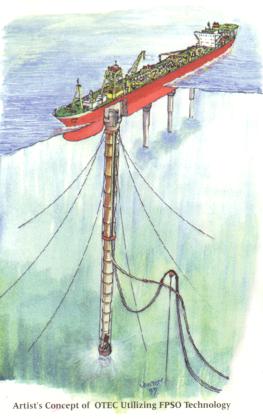
The proposed cold
water pipe (CWP) design is based on work carried out by Jim Wenzel of Marine
Development Associates, Saratoga, California (Wenzel, 1985). This design is
illustrated by the artist's concept on the front cover of this 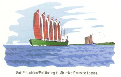 Newsletter. By using a flexible internally pressurized CWP it is
possible to increase the compliance of the system (thus it is better able to
absorb environmental forces) as well as reducing capital cost and simplifying
installation. Modern strong water proof materials, such as hypalon developed for
inflatable boats, would be suitable for the CWP skin. In situ vertical
deployment and recovery of the CWP will allow the floating system to enter
shallow draught areas as well as shipyards for periodic refits. For deep ocean
applications it is likely that only a 6 or 700m long CWP will be required to
reach the desired cold water temp (approx. 4¢X C).
Newsletter. By using a flexible internally pressurized CWP it is
possible to increase the compliance of the system (thus it is better able to
absorb environmental forces) as well as reducing capital cost and simplifying
installation. Modern strong water proof materials, such as hypalon developed for
inflatable boats, would be suitable for the CWP skin. In situ vertical
deployment and recovery of the CWP will allow the floating system to enter
shallow draught areas as well as shipyards for periodic refits. For deep ocean
applications it is likely that only a 6 or 700m long CWP will be required to
reach the desired cold water temp (approx. 4¢X C).
OTEC Power Cycle System
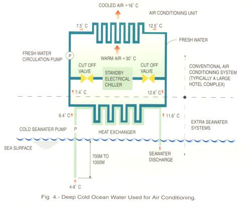
The proposed power system is based on closed cycle OTEC (See Fig. 1.0) with effluent water streams used in a second stage for the production of desalinated water with flash evaporators and surface condensers developed for open cycle OTEC (Vega et Nihous, 1994). The sea-water effluents from the power cycle exhibit a temperature difference (delta T) of approximately 12¢X C. This residual thermal gradient allows the production of significant amounts of desalinated water through a second stage water production system. Smaller quantities of fresh water can simply be generated by using a surface condenser to condense water directly from the atmosphere. In addition, the cool effluent water can be used for air conditioning the on board accommodation areas (See Fig. 3.0). Fresh water production plus low cost air conditioning will help to reduce the operational (OPEX) cost of the whole system.
Unrestrained ¡§ Grazing¡¨ System with Sail Positioning/Propulsion
Deep water FPSOs have proved that mooring in 1,000m+ water depths is perfectly feasible. However, such mooring systems are expensive. In addition, by restricting the OTEC ship to one location it is impossible to use the vessel for applications which require mobility. Such uses may include environmental monitoring, military bases and cruise ships, as well as self transportation of energy products (see later). In addition, an unrestrained OTEC ship can be ¡§weather routed ¡¨ to avoid bad weather, which there is a danger might cause expensive structural damage. Also a non moored configuration, with no electric cable transmission to shore, eliminates vessel excursion restrictions imposed by the electricity export cable.
To avoid a ¡§ grazing ¡¨ OTEC system becoming beam on to the waves, which would result in excessive motions, a positioning system is required. It is here that there is potential to look at the use of sails. This is an interesting concept since, with OTEC being a low efficiency system, parasitic positioning power losses need to be minimized.
Obviously the wind has been used for thousands of years to propel vessels. Although wind is now rarely used for cargo vessels, this is mainly due to commercial requirements for speed and punctual schedules. However, these limitations are not valid for a floating OTEC system.
Recent work (Hansen, 1996) has demonstrated the feasibility of a wind powered 50,000dwt sailing bulk carrier. The basis of this design is that by using hydraulics, rigid sails and computer control, a similar manning level can be achieved compared to a conventional bulk carrier. Thus such a system could be modified for a grazing OTEC system. If rigid sails are used there may also be potential to use the large surface area to mount solar panels. Another system which might have potential is the ¡§ Turbo-Sail ¡¨ which has been demonstrated by Jacques Cousteau on his oceanographic research vessel ¡§ Alcyone ¡¨ .
Sea-Water Discharge Thrust
Sea-water discharge thrust also has some potential for OTEC ship positioning. OTEC power cycle efficiency considerations tend to lead to the use of a final diffuser at the water outlet. Since sea-water discharge thrust is directly proportional to water velocity, the best design for pumping only, leads to minimum thrust capability (Davidson, 1977). However, there is some potential for emergency thrust by varying the size of the outlet nozzle. In addition, even an ideal sea-water system generates some thrust. The potential thrust increases with larger capacity plants and hence higher sea-water discharge. Thus this system may have some potential for the US Navy's proposed Mobile Offshore Base (MOB) - see later. There also may be a possibility of positioning the OTEC ship by ¡§ sailing the CWP ¡¨ using underwater currents, but this requires further analysis and model testing. ¡@
¡§ OTEC 1 ¡¨ (Ex USNS ¡§ Chepachet ¡¨ ) Floating Demonstration System Comparison
It is interesting to compare the proposed 100MW (net) floating system with the third ever floating OTEC test system ¡§ OTEC-1. ¡¨ This 1MW size heat exchanger test bed was incorporated into an ex USNS World War II vintage T2 tanker the "Chepachet". This vessel was of 17,206 tons dead weight capacity with a turbo-electric drive of 5000hp. As part of the conversion the vessel was fitted with two electric azimuth thrusters at the bow and the stern.
During the operational deployment of ¡§ OTEC-1 ¡¨ off Hawaii it proved necessary, during severe weather, to drop the mooring connection to prevent the CWP coming into contact with its gimbal stops. This example proves the attraction of free drifting in heavy weather to minimize environmental loading.
Floating OTEC Operational Areas with Relatively Benign Environmental Conditions
Compared to areas such as the North Sea, the environmental conditions which a deep sea floating OTEC system needs to be designed to withstand are surprisingly modest. This helps to minimize the capital and also the operational costs of a floating system. Dugger et al, 1977 in Avery and Wu (1994) reported that there are three substantial grazing areas, each in the Atlantic and Pacific Oceans, which have been found to have the following suitable characteristics based on the available data:
| Extreme on site design condition with a significant wave height (Hs) of 6m. | |
| Surface current of approximately 0.5 knot or less, deep currents of 0.2 knot or less. | |
| Deep bathymetry which insures there is no possibility of encountering an under-ocean peak extending up to 0.5 mile below the surface. | |
| Available water temperature difference between surface and the deep cold water exceeding 20¢X C with a surface temperature of 25¢X C or greater. | |
| Normal winds of Beaufort force 3 to 4 (7-16 knots). |
For the "Atlantic 1" site a 360,000 square nautical mile area located 300-900 miles off Brazil from 5¢X to 15¢X south latitude is available. The predominant temperatures in this area are 27® 28¢X C at the surface and 4® 4.5¢X C at 762m depth (significantly shallower than the 1000m contour many coastal sites require) giving a delta T of around 23.5¢X C.
Transportation of Energy and Associated OTEC Products
A basic truth of the energy business is that "the mere production of oil (or other energy product) is almost its least value and its least interesting state - markets have to be found." (Yergin, 1991) This was stated by Marcus Samuel, founder of Royal Dutch Shell. Samuel overcame Standard Oil's kerosene monopoly by an integrated strategy which included the building of radical new bulk tankers, which were the first to gain permission to traverse the Suez Canal.
This example from the oil industry highlights the vital importance of straight forward, cheap energy transportation. It is here that radical progress is anticipated over the next few years. This is partly because of the substantial load carrying capacity of mono-hull vessels. Hence, the mobile OTEC system itself can be used to transport energy. Since the CWP can be retracted, the OTEC ship can come into port where electrical energy and possibly also fresh water may be discharged. Alternatively the equivalent of shuttle tankers can be used to transfer OTEC products offshore, thus preventing the need to shut down production. This would be similar to FPSO shuttle tanker offloading, using a power cable instead of an offloading hose.
There are a number of ways in which on board produced energy may be stored. An obvious possibility is battery storage since weight and volume are not too restrictive for mono-hull vessels. Battery technology continues to advance at a fast rate, spurred on by environmental requirements for electric vehicles. This is an area which deserves an in depth study to assess the current state of the art for OTEC applications. It should be stressed that such technology is basically straight forward, with the major challenge being to minimize the capital cost and increase the working life of the battery banks.
An advantage of on board electricity storage is that power would be available to power positioning thrusters for delicate maneuvering or in an emergency. This would be particularly useful if there was a problem with the sail positioning/propulsion system.
Another energy storage option is to use a large high velocity flywheel. This would have the added benefit that the gyroscopic effect of the spinning flywheel could be used to help stabilize the vessel ¡¦ s motions. Again this is a storage option which deserves an up to date appraisal.
Other energy storage possibilities include hydrogen or ammonia production. Ammonia can be synthesized by combining nitrogen with electrolytically produced hydrogen. Most ammonia is currently produced from natural gas. An OTEC ammonia production system could be very attractive to any nation not having an abundant and assured supply of natural gas or oil. The ¡§ Euro-Quebec Hydro Hydrogen Pilot Project ¡¨ plans to use Quebec's surplus hydro-electric power to produce liquid ammonia which would be shipped to Europe in tankers similar to today's Liquefied Natural Gas (LNG) carriers.
A more long term interesting concept is the use of marine photosynthetic micro-organisms for hydrogen production or nitrogen fixation (Mitsui, 1978). This concept might tie in with deep sea water nutrient enriched artificial upwelling, a technology which is normally associated with land based OTEC.
Offshore Fresh Water Production
Many of the land masses in the tropical areas where floating OTEC systems may be operating tend to be short of fresh water. Since fresh water can be generated as part of the OTEC process (for example the open cycle system), it may be commercially attractive to export the water, in addition to on board consumption. Export could either be in the tanks of the offloading shuttle tanker or, looking to the future, in giant flexible bags. Work has been carried out on this concept since 1980 by Nordic Water Supplies and is progressing well (Wiesman, 1996). For a moored system close to land fresh water could be exported via flexible risers. Water export by flexible riser lines between islands in the Mediterranean has been undertaken successfully by Coflexip.
Economic Comparison Between a Marginal Oil Field Development and OTEC
FPSOs have often been used to develop marginal, remote oil fields. An oil/gas field development is considerably more complicated, from a hydro-carbon process equipment point of view, than a simple closed cycle OTEC system. In addition, an OTEC system is much safer and less liable to catastrophic fire and explosion.
Since complex FPSOs have proved profitable it is interesting to compare the economics of a typical marginal oil field with a large OTEC system. This comparison assumes an oil field producing at 50,000 barrels per day (bpd) with a production up time of 98%. The resulting yearly revenue, see table 2, is ¢G223.6M. The floating OTEC has a net capacity of 400MW with an operational up time of 98%. This results in a yearly revenue, see table 3, of ¢G 257.5M.
Table 2.0 - Gross Annual Revenue from a 50,000 bpd FPSO
|
50,000 bpd FPSO |
¡@ |
|
Price per barrel |
¢G 12.50 |
|
Annual availability |
98% |
|
Annual revenue |
¢G 223.6M |
Table 3.0 - Gross Annual Revenue from a 400 MW Floating OTEC System
|
400MW Floating OTEC System |
¡@ |
|
Price per KW.hr |
¢G 0.075 |
|
Annual availability |
98% |
|
Annual revenue |
¢G 257.5M |
Hence it can be seen that a 400 MW system is roughly comparable to a 50,000 barrels of oil per day field. Since the deep water ocean thermal reserves are outside national Exclusive Economic Zones (EEZs), there would be no national taxes to pay. It is worth noting that the United Nations Law of the Sea Treaty came into full effect in November 1994 and has now been ratified by over a hundred nations. Hence outside national EEZs, a floating OTEC plant will be a protected activity under the law of the high seas, similar to fishing.
A fundamental difference between an oil field and an OTEC system is that a marginal oil field will have a limited life, typically ranging from 4 to 15 years. However, an OTEC system has unlimited reserves and is able to carry on producing as long as the process equipment is maintained in working order.
Conventional Power Barge Comparison with OTEC
It is interesting to briefly compare a floating OTEC system with a mobile power barge driven by conventional sources of energy. McDermott International and Stewart and Stevenson in the U.S. are building a gas turbine power barge. The dimensions of this vessel are 284 x 74 feet (86.6 x 22.6m) and it has two gas turbines delivering a total power output of 80 MW. The barge is intended to be moored in protected waters and will cost approximately US$48M.
Deep Sea Environmental Monitoring Station
The world's deep oceans are fairly inaccessible places to monitor. However, regular observation is vital to obtain a better understanding of the contribution these areas make to regional and global environmental systems. A free floating (grazing) OTEC system would provide an ideal platform for ocean research. In particular, the platform could continuously monitor deep and surface water with no weather downtime interruptions. Such monitoring is already being carried out to a limited extent by relatively shallow water bottom fixed oil platforms in the Gulf of Mexico. This is part of B.P.'s "Platforms for Research" project (Beaubien, 1995). The importance of such data is increasing as concerns about climate change and global warming increase. A key advantage for an OTEC floating system acting as a "Deep-Sea Observatory" is that it is possible to obtain data, year after year, from roughly the same area (Wiebe et al, 1993). Oceanographic research vessels are rarely deployed each year to the same part of the deep ocean. Such a system could also prove to be an important element for the proposed Global Ocean Observing System (GOOS) (Flemming, 1994). If global warming leads to more hurricanes, the economic case for better monitoring and prediction will become irrefutable.
Another longer term possibility for a floating OTEC system would be deep ocean mining, for example manganese nodules. For a mining system it might be possible to make partial use of the long deep CWP structure.
Mobile Offshore (Military) Base (MOB)
The US Navy is currently pursuing a major research and development programme into the feasibility of a Mobile Offshore Base (MOB). Such a system could be deployed to trouble spots around the world, particularly for areas where the US no longer has access to land bases. Other military applications could include forward defenses and early submarine detection
For military applications the more self contained the MOB is the better. OTEC could be beneficial since it could provide electrical energy, fresh water and reduced cost air conditioning (See Fig. 4.0). All these products could be generated continuously night and day without requiring re-supply from land. In addition, it might be possible to use the nutrient rich deep ocean water for artificial aquaculture. The sea-food which could be raised could be used to partially feed personnel on board the MOB.
OTEC Potential for Cruise Ships/Casinos>
Modern cruise vessels are huge ships of a size comparable to a floating OTEC system. For example, Celebrity Cruise ¡¦ s ¡§ Century ¡¨ has a length overall of 243.52m and a beam of 32.2m which gives a gross registered tonnage of 70,606 tons (Fulford, 1996). This US$320M. cruise ship can carry 1,778 passengers and 843 crew in great luxury. With so many people on board, operating in tropical climates, the power, fresh water and air conditioning requirements are enormous. An OTEC plant could supply these products with low noise and vibration as well as with zero emissions.
An OTEC powered cruise ship would not be able to enter port unless its CWP was retracted. However, by using daughter fast ferries, passengers could be transported to and from the vessel while it was standing by in deep water. Alternatively gas turbines could be provided to replace the OTEC system when the vessel enters port.
For some applications, such as a floating casino, conference centre, deep water angling resort, or sea food gourmet centre, there might not be any need for the OTEC system to enter port, apart from periodic refit. The OTEC vessel itself would be a good base for deep sea fishing, since the nutrient rich deep ocean water promotes marine life. In addition, the CWP and hull structure would provide a habitat on which organisms could live, such as is provided by artificial reefs.
Moored System Demonstration Project
The required next stage in the development of floating OTEC systems is the building and long term operation of a 5 to 40MW test system. Such a system is probably best moored close to land so that electricity and fresh water can be fairly readily exported to a population centre. Unfortunately, at such a moderate power production capacity, such a system may not prove economic at current energy prices. However, given the potential of the OTEC resource it is worth the investment so that substantial future benefits can be enjoyed.
It is also possible that operational experience from 1 to 5MW land based systems may prove sufficient to side step the requirement for a moderate size floating OTEC demonstration system. Thus it may prove feasible, particularly by incorporating FPSO technology, to go directly to a 100MW size.
Conclusions
FPSO technology represents a remarkably appropriate stepping stone to floating OTEC systems. Accumulated FPSO experience boosts confidence that cost and schedule estimates are achievable and that operational performance and equipment/vessel life can be relied upon.
Overall OTEC represents a potentially lucrative business opportunity for the established oil and power companies. The technology fits in with the Oil Companies established core competencies of offshore energy production, transportation and distribution. As environmental concerns continue to multiply the potential of the technology continues to increase. OTEC would allow the Oil Companies to diversify into a major alternative source of environmentally friendly energy,
For OTEC technology to advance at a faster rate there is a need to increase research, development and demonstration funding. One way which the Oil Industry has adopted for advancing new technology is to set up Joint Industry Projects (JIPs). Such projects combine funding and expertise from Contractors, Classification Societies, Operators and Government Research Organizations. It is suggested that an international JIP on floating OTEC systems, possibly arranged by the IOA, represents an excellent way to move forwards towards commercial success.
Acknowledgments
he great support of my wife, who had a baby during the preparation of this paper, is gratefully acknowledged. Thanks also to Ian Whitby (original artwork), Jim Wenzel, McDermott Marine Construction Ltd. and Mathon Engineering Ltd. for their assistance.
References
Anon., 1996, "Petrobras Awaits First Turret Moored FPSO," Subsea Engineering News, Vol. 13, No. 14, 3rd Oct. 1996.
Avery, W.H., and Wu, C.W., ¡§ Renewable Energy from the Ocean - A Guide to OTEC ¡¨, Oxford University Press, 1994.
Beaubien, D., "Deep Relationships," Horizon - The Magazine of BP's Activities Worldwide, No. 14, June 1995
Brown, M.G., ¡§ An Assessment of the Feasibility of an Integrated OTEC System for Grand Cayman ¡¨ , Procs. IOA ¡¥ 94 at Oceanology International, vol. 5, 8-11 March 1994, Brighton, UK.
Carneiro, P.R.B., "Barracuda Field: New Records for Turret Moored FPSOs", Offshore Technology Conference 1995, OTC 7700
Crager, B., Shumaker, F., and McCabe, C., "Mobile Offshore Production Systems: An Analysis of Technical and Commercial Trends", Offshore Technology Conference, OTEC 8258, 1996.
Daniel, T.H., "Aquaculture Using Cold OTEC Water," Procs. Oceans '85, vol. 2, 1985
Davidson H., and Little, T.E., "Platform Station Keeping Study - Ocean Thermal Energy Conversion Programme", Westinghouse Electric Corporation, Oceanic Division, ERDA contract E (11-1)-4071, Dec. 1977
Deuchler, W.P., Picha, K.G., and Hudon, T.J., "Position Control System Influences on Large Scale OTEC Platform Designs", Procs. 2nd Offshore Mechanics and Arctic Engineering (OMAE) Symposium, 1983
Dugger, G.L., Richards, D., Francis, E.J., and Avery, W.H., ¡§Ocean Thermal Energy Conversion : Historical Highlights, Status and Forecast ¡¨, J. Energy, vol. 7, no. 4, July-August 1983.
Flemming, N.C., "The Economic Case for a Global Ocean Observing System", Second Int. Conf. on Oceanography - Lisbon '94.
Fulford, C., ¡§ Cruising the ¡¦ Interactive ¡¦ Way ¡¨, The Naval Architect, Feb. 1996.
Knud E. Hansen A/S, "Modern Windships - Phase 1 ¡¨ , 75 Bredgade, Copenhagen, Denmark, Nov. 1996.
Mitsui, A., "Marine Photosynthetic Micro-organisms as Potential Energy Resources: Research on Nitrogen Fixation and Hydrogen Production", 5th Int. Ocean Development Conf., Tokyo, Japan, 25-29 Sept. 1978.
Offshore International Newsletter, "Sonat Offshore Commits to build Next Generation Drill Ship," vol. 4, num. 48, May 27th, 1996.
Vega, L.A., and Nihous, G.C., "Design of a 5MW OTEC Pre-Commercial Plant," Procs. IOA '94 at Oceanology International '94, 8-11 March 1994, Brighton, UK
Wenzel, J.G., and Trimble, L.C., ¡§ Flexible Retractable Cold Water Pipe for an Ocean Thermal Energy Conversion System ¡¨ , United States Patent number 4,497,342, Feb. 5th, 1985.
Wiebe, P.H., Moran, D.D., Knox, R., Miller, C.B., McGowan, J.A., "Long-Range Needs for Deep-Sea Platforms: The Deep-Sea Observatory Concept," Marine Technology Society Journal, vol. 27, num. 2, Summer 1993.
Wiesmann, G., "Flexible Bag May Cut Water Export Costs," Lloyds List, 27th June 1996.
Yergin, D., "The Prize - The Epic Quest for Oil, Money and Power", Simon and Schuster, 1991.