Dossier Océan et énergie - Énergie Thermique des Mers
Sommaire IOA News Letters
AIR
CONDITIONING WITH DEEP SEAWATER:
A COST-EFFECTIVE ALTERNATIVE FOR WEST
BEACH, OAHU, HAWAII
BY
T.K.Leraand, J.C.Van Ryzin
Makai Ocean Engineering, Inc. Makai
Research Pier
Waimanalo, HI 96795 USA
Abstract
Deep cold seawater can be a practical and economically viable source of cooling in a centralized air conditioning system. A seawater air conditioning system (SWACS) uses cold sea water from approximately 2000' depth to cool (via a heat exchanger) a centralized fresh chilled water distribution loop serving multiple buildings. At ideal coastal sites, SWACS power savings can approach 80% compared to conventional chillers. This paper summarizes the technical and economic feasibility of such a centralized air conditioning system at West Beach, Oahu, Hawaii. West Beach is an ongoing development of resort hotels with good access to deep cold seawater. Centralized seawater air conditioning is a technically feasible and unsophisticated alternate energy concept that has the potential of significant impact in Hawaii and other similar regions.The installation of large systems at selected locations is economically attractive today.
INTRODUCTION
Deep, cold ocean water is now being recognized and developed as an important resource for use in Ocean Thermal Energy Conversion (OTEC), aquaculture, desalinization, refrigeration, and air conditioning.
These have been active research areas, particularly in the State of Hawaii, where the development of the cold water resource is underway.
The most immediate energy application for deep cold seawater is its use in air conditioning. Because of the proximity to deep cold seawater for many coastal regions in Hawaii and the high demand for air conditioning in large buildings, seawater air conditioning systems (SWACS) are a major potential alternate energy for Hawaii.
The basic concept of seawater air conditioning is to use deep cold seawater to cool the chilled water in one or more air conditioned buildings as opposed to using energy intensive refrigeration systems. The economic viability of the seawater air conditioning is determined by comparing the construction and operating costs of the seawater air conditioning system to the construction and operating costs of conventional air conditioning (A/C) system. This analysis and comparison are the basis of this paper. A specific site in Hawaii is analyzed in detail.
This work has been funded by the Energy Division of the State of Hawaii Department of Business, Economic Development and Tourism.
THE COLD SEAWATER OPPORTUNITY
Large office buildings and hotels are cooled internally by circulating chilled water throughout the building. This chilled water is kept cool with refrigeration units (chillers) that require electricity to operate. Chilling this water requires approximately 0.9 peak kW per hotel room. A hotel complex with 1000 rooms could have a peak electrical demand for air conditioning of 1 megawatt or larger. Therefore, operating chillers to keep the chilled water at 45¢K comes at a significant power cost to the hotel.
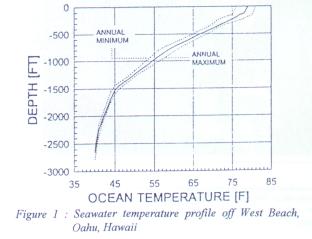
Most of the air conditioning demand in Hawaii is in coastal areas and many of these areas have access to deep cold seawater. Seawater temperatures of 42¢K and below are available starting at water depths of 2000 ft. Figure 1 illustrates a typical seawater temperature profile for Hawaiian waters. The deep water portion of this profile changes very little seasonally and therefore cold seawater is available on a year round basis.
THE SITE
West Beach, Oahu, Hawaii has been selected for this initial in-depth analysis since it is a major development on West Oahu with excellent access to deep cold seawater and comprising of resort hotels, apartments and commercial space. The planned size is more than sufficient to justify the installation of a major SWACS. Also, this development has not been completed, so new development has the opportunity to take full advantage of the SWACS by eliminating or minimizing the installation of conventional A/C systems.
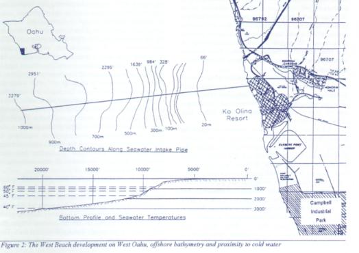
Figure 2 shows the location of West Beach on the island of Oahu and details of the offshore bathymetry. In 1982-5 Kahe Point was the location for a major Ocean Thermal Energy Conversion (OTEC) design sponsored by the Department of Energy. This OTEC plant was never built, but much of the environmental data remains for this area and has been the basis of this study.8 The bathymetry shown in Figure 2 comes from this work. This profile shows depths, distances, and bottom seawater temperatures.
Makai estimated the air conditioning needs based on West Beach Estates plans. The plan indicates the number of hotel rooms and apartment units for each parcel. Only parcels assigned for hotels, medium density apartment buildings and commercial areas are considered in this report for a centralized SWACS.
Five baseline scenarios were considered, varying in A/C demand and configuration as follows:
SEAWATER FOR COOLING
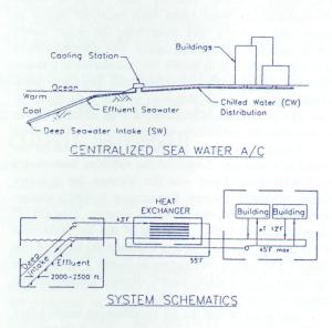
A basic seawater air conditioning system is illustrated in
Figure 3. The building, or buildings, to the far right are identical internally to buildings cooled with conventional A/C. Chilled fresh water moves through these buildings with the same temperatures and flows of conventional systems. The chilled water loop in this system, however, is not cooled by a conventional chiller. The low temperatures in the chiller loop are maintained by passing this fresh water through a counter-flow heat exchanger with the primary fluid being deep cold seawater. The two fluids do not mix but are on either side of a titanium plate that transfers the heat from one fluid to the other.
The left side of Figure 3 shows the seawater supply system. The seawater intake brings in water at a temperature lower than the temperature maintained in the chilled water loop. Once the seawater passes through the heat exchanger(s), it is returned to the ocean through a discharge pipeline.
SEAWATER SUPPLY SYSTEM:
The seawater supply system includes an intake pipeline, a pump station and an effluent line. The objective of the seawater supply system is to transport the cold seawater to the shoreline where it enters a central cooling station. The seawater is drawn from the deep ocean through the cold water pipe, is pumped through the cooling station and then returned to the ocean through the effluent line.
The seawater supply system is the major component of a SWACS. The deep water pipeline cost is the major capital expenditure, and it is also the greatest risk. Early studies of SWACS identified the advantages of this form of A/C, but the uncertainties associated with the cold water pipeline were too great to realistically evaluate the costs or to recommend its construction. However, during the last decade, the State of Hawaii has installed and is operating several deep water pipelines at Keahole Point, Hawaii. These pipes bring in deep, cold seawater for OTEC and aquaculture research. The largest pipeline installed is 40" in diameter, with an intake at 2150'.10 A pipeline of this size, if used exclusively for air conditioning purposes, could supply almost 5000 tons of air conditioning at Keahole Pt. and replace over 4 MW of electrical power. This pipeline has been in continuous operation for over 8 years. A smaller, 12" diameter pipeline of the same design provided reliable service to Keahole for over 12 years in spite of its "temporary" 2-year design life. A new pipeline, 55" in diameter reaching 3000' depth is currently being designed and nearshore construction is underway.
The basic pipeline design assumed for this study is identical to the pipeline approaches used at Keahole Pt. The bathymetry is similar with a wide shelf of relatively low slope followed by a sharp escarpment. The designs used on Hawaii can be applied to Kahe with a high degree of confidence.
All of the seawater intake pipelines designed for Keahole Point, Hawaii use polyethylene as the pipeline material. Polyethylene has significant advantages for these pipelines in that it is inert and will neither corrode nor contaminate the water. Polyethylene lengths are heat fused together to form a long, continuous pipeline with joints that are as strong as the pipeline itself. Polyethylene has excellent strength and flexibility and is buoyant in water. These characteristics allow a great deal of design flexibility and deployment ease. Pipes as large as 63" in diameter are commercially available.
Makai's approach for a deep water pipe deployment is to install the pipe quickly. The pipeline is designed for the deployment process since this represents the major cost and risk of the installation. The pipeline is assembled complete on shore, launched floating using the pipeline to support all anchors and fastenings, towed to the site, and controllably submerged while carefully monitoring pipe tensions and pressures. The procedure is stable and reversible.An effluent pipeline is used to return all the seawater back to the ocean. The effluent is uncontaminated by the SWACS process. The effluent temperature would be approximately 57¢K, considerably cooler and more dense than local surface waters. Deep seawater also has higher nutrients than surface water. The effluent pipe is similar in design and size to the deep water pipeline. It discharges its water at a depth of 490', well below the escarpment off Kahe Pt. At this depth and along this very steep slope, the dense effluent water will continue to sink and mix with the ambient water ( approximately 68¢K. The discharge depth is well below the photic zone and with rapid dilution, the environmental impact would be minimal. This approach is consistent to discharge methods proposed for OTEC plants, dealing with total water flows that are colder and with volumetric flows that are orders of magnitude greater than those proposed for SWACS.
CENTRAL COOLING STATION
The central cooling station is the interface between the seawater side of the SWACS and the chilled fresh water loop. Heat is transferred from the fresh water to the seawater. The primary components in the central cooling station are the heat exchanger, the fresh chilled water pumps and a chiller (optional). This section discusses the heat exchangers and the potential of coupling a chiller into the SWACS.
The proposed arrangement is for a single central cooling station for West Beach. As an alternative, the SWACS could be designed with distributed chiller stations. Seawater could be pumped to each building which would have individual heat exchangers for cooling its fresh chilled water. This option was not selected for West Beach because of the economy of having one centralized heat exchanger that could be easily maintained and controlled. Secondly, with elevation variations on the site, an open loop seawater supply could have significant energy losses in pumping head that could be avoided with a closed fresh water loop.
The heat exchanger transfers heat between the chilled water and the seawater. Titanium plate heat exchangers have been selected for this conceptual design. Titanium plate heat exchangers are very durable and well proven for heat transfer involving seawater; life expectancies are in excess of 20 years. Titanium flat plate and also shell and tube heat exchangers are in operation at the Natural Energy Laboratory of Hawaii. These titanium heat exchangers have been the subject of long term corrosion and biofouling experiments for OTEC research. With deep seawater, there are neither biofouling nor corrosion problems associated with titanium.
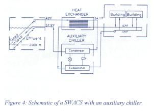
If the seawater supply temperature is too high and the fresh water cannot be cooled economically through the heat exchanger, it becomes necessary to provide additional cooling of the fresh water. This is the case when the deep water pipeline cannot reach the depths required economically, or the overall SWACS is so small that the seawater temperature rise through the cold water pipe leaves the seawater too warm on the surface.
A seawater cooled chiller unit can be used to extract additional heat from the freshwater, and dispose it to the effluent seawater. This arrangement is shown in Figure 4. The coefficient of performance for a traditional chiller coupled with a cooling tower operates at 4.1 but the chiller operating with seawater cooling of the condenser operates at about 8.2. Hence, the cooling is achieved at half the conventional electrical cost.
CHILLED WATER DISTRIBUTION
A single branch network with a supply line and a return line was selected for this study. The two pipelines are buried in the same trench. The system contains a fixed amount of fresh water that is cooled in the central cooling station, before it is supplied to the hotels, through the supply line. The return line carries the water back after it has circulated through the hotel. The distribution system operates at a constant flow. During low loading, some chilled water is bypassed between the two lines to keep water flow constant and to maintain a sufficiently low supply temperature. The pumps are located adjacent to the central cooling station.
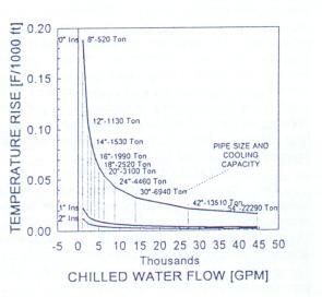
Because of the extensive networks required for West Beach, an insulated ductile iron pipe was selected for the distribution system. This is a standard commercially available material. The insulation is 2" of polyurethane foam covered with either PVC or polyethylene. The insulation on these pipelines is quite effective and large distributions systems can be operated with minimal temperature rises in the chilled water supply. Figure 5 shows the temperature rise in 1000' of pipeline operating at various flows and with differing amounts of insulation. Note that there is a large difference between insulated and non-insulated pipes and that total flow has a major impact.
SWACS OPTIMIZATION
The design and integration of SWACS components is highly iterative, and depends on the operating design criteria and the site specific conditions. The primary requirement of the SWACS was cooling demand (tons) and operating chilled water temperatures.
In the process of optimizing the system, a SWACS design program was developed. The objective of the SWACS design program was to select system operation parameters to maximize overall technical and economical performance. Typical of this optimization were the following:
¡@
|
Seawater supply temperature: The temperature of the seawater entering the cooling station has a large impact on the capital cost of the system and annual savings. For each scenario, the seawater supply system and the central cooling station were analyzed for multiple seawater intake temperatures. Cooler seawater results in a more expensive seawater supply system, but results in a less expensive cooling station, and lower operating costs. The system lifetime costs were minimized by selecting an optimum seawater supply temperature. | |
|
Size of heat exchanger and auxiliary chillers: For each scenario at West Beach, the value of using |
auxiliary chillers was determined. The size and costs of the heat exchanger and auxiliary chillers were determined such that the lifetime cost was at a minimum. For a given seawater supply temperature, chilled water temperature and cooling load, there is an optimum combination of heat exchangers and chillers. For cool seawater supply temperatures and large systems, the chiller can be eliminated and the cooling of the chilled water takes place in the heat exchanger. At locations with warmer seawater temperatures or with small demand, it becomes desirable and sometimes necessary to use chillers instead of increasing the size of the heat exchanger to take the cooling load.
Typically, the SWACS design started by determining the required flow of chilled water into each hotel, given the chilled water operating temperatures. The flow through the chilled water distribution system was then determined, and the distribution system was designed in order to determine the temperature of the chilled water into the network and the returning temperatures for various utilization ratios and pumping power.
The cooling station was designed by assuming a seawater supply temperature and flow rate into the station. The heat exchangers and chiller sizes were determined and optimized in order to provide sufficient chilled water cooling capacity at the lowest cost. The seawater supply system was designed, and the capital and operating costs established for the entire system were then determined. By altering the seawater supply temperature, and comparing lifetime costs for the various options, the SWACS could be optimized.
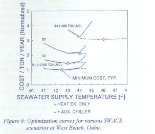
Figure 6 shows the results of this optimization process. The first four scenarios for West Beach, ranging in size from 12,700 tons to 1300 tons are each optimized. The curves illustrate the relative annual costs per ton for the seawater supply system and the central cooling station versus the seawater supply temperature. Costs for the distribution system were not included because this is a constant for each scenario. The relative lifetime costs in Figure 6 were estimated based on the annual operating cost (energy and maintenance) plus 13.2% of the total capital costs (an approximate value coming from the economics presented later).
For each scenario, the costs were computed for using a heat exchanger only and for using an optimum combination of heat exchanger plus auxiliary chiller. As the seawater temperature rises, the ability of the heat exchanger alone to provide the fixed output chilled water diminishes and these costs soar.
The optimum for each design is the minimum on each curve. For Scenarios 1 through 3, the heat exchanger only option was selected. Even if the auxiliary chillers could give a modest boost in economic performance, the simpler system without the auxiliary chillers would be chosen. With Scenario 4, however, the system would not operate with heat exchangers only.
Scenario 5 was not considered for use with an auxiliary chiller. The purpose of this scenario was to investigate the value of operating a SWACS as a higher differential temperature in the chilled water loop. It is identical to Scenario 3 but with a differential chilled water temperature of 16¢K as opposed to 12¢K.
ECONOMICS
The basis for the economic comparison of SWACS with conventional A/C is the capital cost and operating cost of each component in the system. The capital cost estimates are based on quotes from manufacturers, cost estimates from contractors, estimating manuals, communication with air conditioning design engineers, past projects, and engineering estimates. The significant parameters for the operating cost of SWACS and conventional A/C is the electricity cost, efficiency of pumps, motors, chillers and cooling towers. These parameters were defined based on communication with Hawaiian Electric Company (HECO), air conditioning design engineers, operators and manufacturers. The basis for all the cost estimates is 1994 dollars. Component costs include shipping to Hawaii, and construction and labor cost are based on quotes from local contractors and past projects in Hawaii.
The accuracy of West Beach SWACS costs vary, depending upon the component or system being priced. Offshore pipeline costs and onshore distribution cost estimates are probably within 20%; the centralized chiller station costs are probably within 15%; operating costs (excluding electricity) are probably within 30%; and electrical rates are current quotes from the Hawaiian Electric Company. Overall, costs are probably within 20%. Average costs for conventional A/C systems are only slightly more accurate, for these costs vary greatly relative to the complexity and quality of the system.
The economic model used to evaluate the economic difference between seawater air conditioning and conventional air conditioning is based on an analytical procedure developed by the Electric Power Research Institute (EPRI) in their Technical Assessment Guide [TAG].4 The TAG model is an economic analysis method of comparing two alternate energy systems with different capital and operating costs. The TAG method determines the revenue required of an energy system; it is the current electric utility industry practice.
EPRI's TAG economic model determines the revenue required of an energy system. The revenue required is the minimum income needed to cover all system costs. These costs include interest and principal payments on loans, a minimum acceptable return on equity, taxes, depreciation, operating cost, lead time for construction, occasional replacement of equipment, maintenance and operation costs. The general method involves projecting these costs over the useful life of the investment using present value analysis to account for the time value of money. When comparing two alternate systems, the system with the lowest revenue requirement is the best alternative, all other things being equal.
In this analysis we are comparing a conventional A/C system to a seawater air conditioning system to determine if, where and when a SWACS can be competitive. The TAG method of analysis, when applied to the conventional A/C system, determines the true cost of operating that system for an individual hotel owner or building operator. The revenue requirement in this case is the maximum amount that a building operator would be willing to pay for a substitute air conditioning system. By applying the TAG model to the SWACS, the total operational cost, debt service and return to investors is included into the revenue requirement. If the revenue requirement for the SWACS is less than that of a conventional A/C system, then the SWACS is a more viable economic alternative.
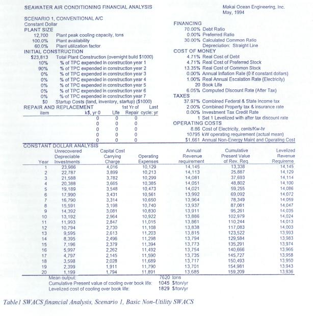
Table 1 shows the input and output of the TAG method of revenue requirement analysis for the SWACS, Scenario 1. The top of the table shows all the input and the lower portion of the table is the revenue requirement analysis in constant dollars. The size of the plant is 12,700 peak tons with a mean output of 7,620 tons. The initial construction cost is approximately $25 million and there is periodic reinvestment for seawater and cold water pumps. The annual operating cost is $840,000 a year and the electrical demand is 1177 kW.
The lower portion of Table 1 shows the revenue requirements. On the far left are the unrecovered depreciable investments at the beginning of each operating year. The capital cost carrying charge in the next column includes the interest and principal payments on debt, a return to investors, taxes on the equity return, depreciation and any reinvestment required. The operating expenses shown are primarily maintenance and power costs. Power costs are escalated at 1 percent per year in line with HECO projections.5 The sum of the capital cost carrying charge plus the operating cost expenses is the annual revenue requirement for this alternative. This is the minimum revenue required to pay all expenses and satisfy equity investors.
The next column is the cumulative present value of this revenue requirement. Each year's revenue requirement is converted to the beginning of the first year present value. The levelized revenue requirement in the final column is the fixed annual dollar income that is equivalent to the cumulative present value for that year. The levelized revenue requirement for year i represents a constant annual payment, which collected over the first i years of book life, would have the same present value as the sum of actual year-by-year revenue requirements during the same period.
The final economic value that was used for comparing one alternative to another was the levelized cost of cooling over book life. The levelized revenue requirement in the 20th year was divided by the mean output of the air conditioning facility to yield a levelized cost in dollars per ton per year. This is the bottom line in Table 6.1.
A similar analysis was performed on conventional A/C. To compare SWACS vs. conventional A/C for new construction, total levelized costs can be compared. Toshow the economic advantages of SWACS to a building with an existing conventional A/C system, the SWACS levelized costs must compare favorable to the conventional A/C costs for operation and maintenance only, excluding capital costs.
The levelized cost for the Scenario 1 SWACS is 665$/ton/yr while the levelized cost for the conventional A/C, including capital, is approximately three times that value at 1829$/ton/yr. For the operation and maintenance of conven
|
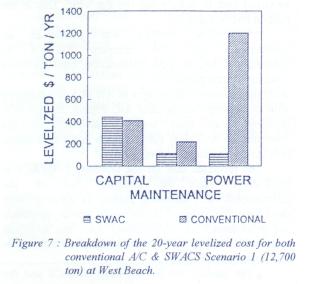
The capital cost for the large SWACS and the capital cost of a conventional system (chillers plus cooling towers) are nearly identical. Therefore, the major cost of the SWACS is almost matched by conventional A/C. | |
|
The maintenance of the SWACS is less than a conventional system A/C. The conventional A/C is multiple discrete systems in many different buildings, so a SWACS centralized cooling station is more efficient to maintain.. Also, the SWACS is not as complex, most of its cost is in pipelines, not compressors. | |
|
The major difference between the two systems is in power consumption. Power savings for the SWACS are nominally 80%. The power cost alone for conventional A/C dominates the combined capital, maintenance and power cost of a SWACS of this size. |
There is no economy of scale for the conventional A/C systems at West Beach. Scenario 1 consists of 16 individual buildings, and for conventional A/C, each requires an independent system operating at the same efficiencies and levelized cost.
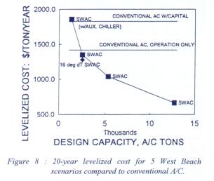
This independence of size does not hold true for SWACS. Levelized costs per ton for a SWACS dramatically rise as the system becomes smaller. This is because the unit cost of delivering seawater through a pipeline increases as the pipeline size diminishes and the thermal performance of the pipeline degrades with lower flows of seawater. There is therefore a minimum economic size for a SWACS.
Figure 8 illustrates the impact of size on the SWACS levelized cost. The levelized cost for the four SWACS scenarios ranging from 1300 tons to 12,700 tons are plotted. In addition, a single point is shown representing Scenario 5, the 2500 ton SWACS using a 16¢K temperature differential through the serviced buildings. Two horizontal lines represent the cost of conventional air conditioning both with and without capital cost included.
Basically, a SWACS is extremely competitive in a large size and marginally competitive or not competitive at all in very small sizes. The economic incentive is to make the system as large as possible.
If there were 2500 tons or more of installed air conditioning today at West Beach, a SWACS could be installed to sell chilled water to the buildings at a cost equal to or better than their present cost to chill A/C water.
The same type of comparisons can be made for new buildings with new air conditioning needs. If there were 1500 tons or more of planned A/C construction at West Beach, a SWACS could be provided that would be competitive. If the system is much larger than 1500 tons, the SWACS would be very competitive.
CONCLUSIONS
|
Centralized seawater air conditioning is a technically feasible and unsophisticated alternate energy concept that has the potential of significant impact in Hawaii. The installation of large systems at selected locations is economically attractive today. | |
|
SWACS are not complex and are a low technical risk. All components are state-of-the-art. | |
|
The seawater pipeline is the highest risk element of a SWACS as it would be difficult to repair quickly if it failed. Similar pipelines have been successfully installed at Keahole, Hawaii. When designed for long lifetimes, these pipelines have provided reliable service. | |
|
SWACS larger than 1500 tons can be built for West Beach that provide chilled fresh water to the serviced buildings at 45¢K. Smaller systems would require auxiliary chillers. | |
|
Large seawater pipelines perform better thermally than small ones. The temperature rise in smaller pipes has to be compensated with auxiliary chillers. | |
|
Power savings for a large SWACS as compared to a conventional A/C system are considerable. For systems not requiring an auxiliary chiller, savings are over 80%. |
|
Distribution A/C losses are minimal. With insulated piping, these losses are kept below 0.5%. | |
|
Using auxiliary chillers with a warmer seawater intake temperature is not a large SWACS economic penalty. This opens the door for other sites that may not have ideal access to deep seawater. | |
|
Large SWACS costs are typically broken down into 67% capital carrying costs (41% seawater supply, 18.4% distribution, 7% cooling station); 17% maintenance and 16% power. | |
|
Conventional A/C costs are typically 67% power costs. | |
|
In comparing large SWACS to conventional A/C, the capital requirements of the entire SWACS are comparable to the capital needs for the chillers and cooling towers of a conventional A/C system. Maintenance costs of the less sophisticated and centralized SWACS are less and the power costs are dramatically less. The power cost requirement for conventional A/C alone is larger than all the costs associated with a large SWACS. | |
|
In comparing the revenue requirements of SWACS to the operating costs alone (no capital costs) of large conventional A/C systems, SWACS can be competitive at sizes larger than 2500 tons. Very large systems at 12,000 tons can cut the costs in half. | |
|
In comparing the revenue requirements of SWACS to the total costs, including capital, of large new conventional A/C systems (chillers and cooling towers), SWACS can be competitive at sizes larger than 1500 tons. Very large systems at 12,000 tons can cut the costs by two-thirds. | |
|
Two major factors dominate SWACS economics: cooling capacity size and pipeline costs. Cooling capacity dominates and can overcome other site disadvantages. Small systems (less than 1000 tons) will probably not work at even the most ideal location. |