Dossier Océan et énergie - Énergie Thermique des Mers
Sommaire IOA News Letters
Sub-Sea Fluid Piping Heat Transfer Calculation Procedure for Piping System Optimization
by
BRUNO
?ALI? and NIK?A FAFANDJEL
Faculty of Engineering University of
Rijeka
Department for Naval Architecture and Ocean
Engineering
Croatia
JULIJAN DOBRINI?
Faculty of Engineering
University of Rijeka
Department for Naval Architecture and Ocean
Engineering
Croatia
ABSTRACT
While transferring fluids through sub-sea piping, those are exposed to changeable surrounding water temperature and sea current velocity. Therefore heat transfer from piping towards outer surrounding water or from outer surrounding water towards piping occurs. The objective is to calculate more precisely total heat energy transfer along sub-sea piping. For better understanding of hydraulic losses over long piping a special mathematical model was defined. The model is based on definition of finite piping segment heat energy transfer.
Corresponding computer software for heat energy transfer calculation was developed and tested, mainly intended to solve specific ecology problems influenced by pollutant fluids blocked in sunken vessel tanks.
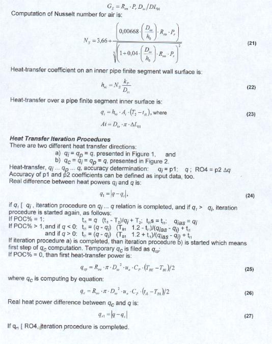
Obtained results' analysis enables defining shape (cross sections) and variables such as: dimensions of the pipeline, wall thickness and material, and insulation thickness and material, etc.
As conclusion authors suggest that by interactive calculation based on developed software it is possible to perform the analysis of piping heat transfer with the objective of whole piping system optimization.
Computer processing results are graphically presented in three dimensions (3D) with the possibility to change any pair of above mentioned variables, that is illustrated on a deep sea piping system example.
INTRODUCTION
Authors of this article solved specific problem that correspond to ecology problems influenced by pollutant fluids blocked in sunken vessel tanks. Preparation procedure for extraction of pollutant fluids from sunken vessel tanks, as well as theoretical and professional background was described in (?ali ?> BRUNO [1]). For prediction of extracting power that is necessary for pollutant transfer, "AntiPollutant" software was developed and tested. Usage possibilities of "AntiPollutant" software in marine technology have been described in (?ali ? BRUNO [2]). An overlook to new structures and devices in coastal zone and sub-sea, has been described in (?ali ? BRUNO [3]). On that base usage of different long piping heat transfer can be solved. In surface and underwater offshore plants various long piping exposed to environmental conditions are used for water transfer. For better understanding of hydraulic losses along such piping resulting in required transfer power, complex theoretical approach, because of additional heat transfer problem is presented.
For long vertical underwater piping developed "AntiPolluttant" software can be used successfully taking under consideration:
| predicted or experimental variation of surrounding sea current velocity along piping has to be prepared for cubic spline approximation, | |
| predicted or experimental variation of surrounding water temperature along piping has to be prepared for cubic spline approximation, | |
| Physical properties of water have to be additionally prepared in table form for automatic computer approximation procedure. |
Changes of pipeline outer fluid temperature and flow speed that are obtained on basis of local environmental properties monitoring are processed by computer using cubic spline method. From those curves, relevant mathematical results are obtained for mean values of outer temperature and flow speed, for every mathematical (finite) segment of the pipeline.
SUB-SEA FLUID PIPING HEAT TRANSFER CALCULATION PROCEDURE FOR PIPING SYSTEM OPTIMIZATION
Mathematical Model of Heat Transfer between Pipe Finite Segment and Environment
Figure 1 shows geometrical data of pipe finite segments for two heat transfer stages: a) heat transfer into a finite fluid segment from outer environmental fluid, b) heat transfer from a finite fluid segment to environmental fluid.
Figure 2 shows qualitative changes of heat transfer temperatures for two heat transfer stages: a) heat transfer into a finite fluid segment from outer environmental fluid, b) heat transfer from a finite fluid segment to environmental fluid.
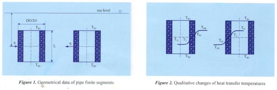
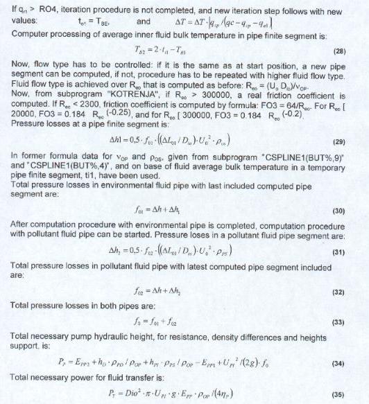
Figure 1 and Figure 2 have been used, as base for defining of mathematical model that will be described later on.
Main heat power equations consist of heat transfer in an outer region (q), over a pipe wall surface (qp), heat transfer in an inner region (qi), and finally heat transfer between inlet and outlet pipe finite segment surfaces (qc):
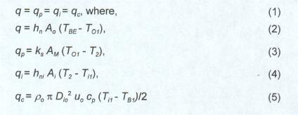
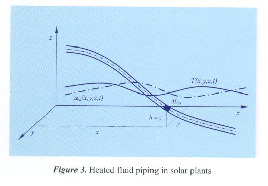
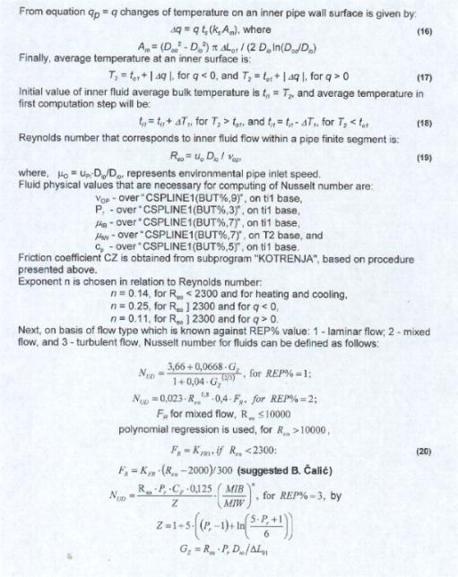
Figure 3 shows heated fluid piping in solar plants exposed to environmental conditions as base that can be used for heat looses calculation in solar plant piping/channels.
Corresponding heat transfer energy can be expressed by equations:

where:
¡@
£GT < 0 - negative heat energy - outcome heat energy (loosed energy) in pipe finite segment,
£G T > 0 - positive heat energy - income heat energy to pipe finite segment,
G T = 0 - there is no heat energy exchange in a correspond pipe finite segment, except that heat energy which is transforming from hydraulic losses, and has reflection to making higher thermal energy level in computed pipe finite segment.
Differences Between Underwater and Surface Piping
There are three basic differences between underwater and surface piping:
| Underwater environment | Surface/land environment | |
| Environmental fluids | salt/fresh water | air | Environmental flows | sea currents | winds speed |
| Hydrostatic pressure | environmental water/ | warm water, air pressure |
| pollutant | neglected |
Conclusion
Described computer tested mathematical model is mainly intended for computation of heat transfer in way of underwater vertical pipes.
Obtained results' analysis enables defining shape (cross sections) and variables such as: dimensions of the pipeline, wall thickness and material, and insulation thickness and material, etc.
It is suggested that with interactive calculation based on developed software is possible to perform the analysis of piping heat transfer with the objective of whole piping system optimization.
Obtained results can be graphically presented in three-dimension (3D) with the possibility to change any pair of mentioned variables.
In case of land piping under consideration, main part of presented software can be successfully used taking in consideration:
| variation in pipe height along piping has to be prepared for a cubic spline approximation, | |
| predicted or experimental (statistic) variation of wind speed along piping has to be prepared for cubic spline approximation, | |
| predicted or experimental (statistic) variation of air temperature along piping has to be prepared for cubic spline approximation, | |
| Physical properties of air as well as heated transported water have to be additionally prepared in table form for automatic approximation procedure. |
In case that pipes of cross sections different than circular are used, it is necessary to use modified heat loses formulas.
NOMENCLATURE
| A0 |
, |
m2 |
Heat transfer surface of outer pipe finite segment surface |
| AM |
, |
m2 |
Heat transfer surface of average logarithmic pipe finite segment surface |
| cp |
, |
Jkg-1K-1 |
Thermal conductivity by constant pressure |
| Dio |
, |
m |
Pipe finite segment inner diameter |
| Doo |
, |
m |
Pipe finite segment outer diameter |
| EPP1 |
, |
Nm-2 |
Total environmental fluid pressure related to reference computational density |
| EPP2 |
, |
Nm-2 |
Total pollutant fluid pressure related to reference computational density |
| hf |
, |
m |
Middle depth of a pipe finite segment; |
| hn |
, |
Wm-2K-1 |
Heat-transfer coefficient on pipe finite wall segment outer surface |
| hni |
, |
Wm-2K-1 |
Heat-transfer coefficient on pipe finite wall segment inner surface |
| Kp |
, |
WmK-1 |
Thermal conductivity |
| ks |
, |
WmK-1 |
Thermal conductivity of a pipe finite wall segment; |
| NUD |
, |
- |
Nusselt number |
| Pe |
, |
- |
Pecklet number |
| PP |
, |
W |
Needed power for pollutant fluid pumping |
| Pr |
, |
- |
Prandtl number |
| PT |
, |
W |
Total necessary power for fluid transfer |
| qc |
, |
W |
heat flow through the pipe finite segment |
| qi |
, |
W |
heat flow on pipe finite wall segment inner surface |
| qp |
, |
W |
heat flow in pipe finite wall segment |
| Reo |
, |
- |
Reynolds number |
| T01 |
, |
C |
Average temperature at a pipe finite wall segment outer surface |
| T2 |
, |
C |
Average temperature at a pipe finite wall segment inner surface |
| TB1 |
, |
C |
Average bulk temperature at pipe finite segment inlet cross section |
| TBE | , |
C |
Average inner fluid bulk temperature at half height of a pipe finite segment |
| Tf | , |
ms-1 |
Average environmental fluid flow speeds |
| Ti1 | , |
C |
Average inner fluid bulk temperature at a computation finite segment |
| ts | , |
m |
Pipe finite segment wall thickness |
| Ums | , |
ms-1 |
Average environmental fluid flow speeds |
| Up1 | , |
ms-1 |
Average speed of pollutant flow at the pipe outlet |
| Wq | , |
size=4>J |
Heat transfer energy |
| Wqc | , |
size=4>J |
Heat transfer energy through pipe finite wall segment |
| Wqi | , |
size=4>J |
Heat transfer energy through pipe finite wall segment inner surface |
| Wqp | , |
size=4>J |
Heat transfer energy through pipe finite wall segment outer surface |
| Po | , |
kgm-3 |
Environmental fluid density |
| U1B | , | kgm-1s-1 | Average fluid dynamic viscosity of pipe finite segment |
| U1W | , | kgm-1s-1 | Average film fluid viscosity |
| £G L0 | , |
m |
Pipe finite segment length |
| Vop | , |
m2s-1 |
Average fluid kinematics viscosity of pipe finite segment |
| Pop | , |
kgm-3 |
Pollutant fluid density |
| £bP | , |
- |
Pump efficiency coefficient |
| Pps | , |
kgm-3 |
Pollutant fluid density of pipe finite segment |
| £G T | , |
- |
Intial step of a pipe finite wall segment outer surface temperature variation |
ACKNOWLEDGMENTS
The authors wish to express gratitude to the Faculty of Engineering University of Rijeka and specially to the dean Prof. Bernard Frankovi face="Times New Roman" color=#000080 size=1>? , D. Sc. for their understanding and support to the research and development activities in field of naval architecture and ocean engineering.
Herewith, authors also express their gratitude to the Government of the City of Rijeka and specially to the major Mr. Slavko Lini face="Times New Roman" color=#000080 size=1>? for their help and comprehension to enable participation to IOA'99 conference in IMARI.
The authors also acknowledge the help and participation regarding performed experiments with the prototype of the "Ecology Underwater Device" developed on basis of Mr. Calic invention to the "Brodospas" - Towing and Salvage Company from town Split.
Special thanks goes to the Shipyard "Uljanik"- Pula for their participation in construction and testing of mentioned device prototype.
REFERENCES
1. ?ali ? B. "Prilog metodama rje ? face="Times New Roman" avanja ekologije voda primjenom specijalnih autonomnih sustava za odstranjivanje polutantnih fluida iz potopljenih spremnika (Contribution on Solving Water Ecology by Special Autonomous Systems for Extracting of Pollutant Fluids from Sunken Vessel Tanks)", Dissertation, Faculty of Engineering University of Rijeka, Rijeka, pp1-122 (1994)
2. ?ali ? face="Times New Roman" color=#000080 B. "Usage Possibilities of the AntiPollutant Software in the Marine Technology", Proceedings. International Conference Adriatic Coastal Zone and Sub-sea - Real Challenge for Croatian Tourism, Opatija 1995, Croatian Academy of Sciences and Arts & Faculty of Engineering University of Rijeka, Rijeka, pp123-131 (1995)
3. ?ali ? face="Times New Roman" color=#000080 B. "Nova sredstva u priobalju i podmorju u turisti size=1>?koj ponudi - New Devices in Coastal Zone and Subsea in Tourist Offer", Proceedings. International Round Table Adriatic Coastal Zone and Subsea - Real Challenge for Croatian Tourism, Opatija 1994, Croatian Academy of Sciences and Arts & Faculty of Engineering University of Rijeka, Rijeka, pp27-33, and 99-103 (1994)