Dossier Océan et énergie - Énergie Thermique des Mers
Sommaire IOA News Letters
Energy from seawater: A self-sustained diffusive pump.
By: Lars G. Golmen* and Benoit Cushman-Roisin**
1. Background
The concept of creating artificial upwelling or exploiting thermal differences in the tropical ocean has been studied for decades in connection with mariculture and power generation for various applications. Much of this activity derives from the paper by Stommel et al. (1956) who showed that a flow can be maintained within a vertical pipe extending from warm and salty surface waters to colder and fresher deep waters in the tropical ocean, if the pipe flow is subject to some initial priming. This inspired the OTEC (Ocean Thermal Energy Conversion) program, which was launched in the 1970s and through which several full-scale experiments have been performed (Avery and Wu, 1994).
One way of creating similar upwelling in fjords, which have reverse thermal and saline stratification, is with a system that contains the flow within a set of vertical and horizontal tubes. This approach was described by the present authors several years ago (Golmen and Cushman-Roisin, 1992). That paper gave a theoretical presentation of the concept and discussed a few possible variations of the basic design, but in no detail. Some possible applications to fjords were also suggested, but the study was not followed up due to lack of priority and funding.
Last year, a new report (Golmen, 1998) was published that included a brief review of the diffusive-pump concept and a description of some possible practical applications in Norwegian waters. In the present article, we summarize that report, supplement its text, and describe a laboratory prototype and tank experiments performed recently at Dartmouth College, USA.
Due to the dominance of hydroelectric-power production in Norway, research on alternative energies has traditionally been neglected in that country. But, there are now signs that this situation may be changing in the near future, as indicated by new developments in the international arena, including efforts to reduce greenhouse-gas emissions.
In 1993, the Norwegian Research Council (NFR) launched a new program on heat pumps, which was the subject of some ongoing research activity, mainly undertaken by SINTEF in Trondheim. The NYTEK programme (on ¡§ Effective and renewable energy technologies ¡¨), which supported the present study to promote research on new source of energy, was launched by NFR in 1995 (NFR, 1995), and by 1997 another 5-year programme had been established on energy/electricity use, including some focus on renewable energies.
Although it is probably of minor importance in solving general problems, the diffusive pump may be one of many technologies that can stimulate positive thinking in an alternate direction, and, in certain areas, may actually be of significance either as an energy supply or as an energy converter.
2. The concept of the diffusive pump
It has been known for a long time that, under certain hydrographic conditions, it is theoretically possible to maintain a continuous vertical flow of seawater in a tube crossing the pycnocline (vertical density gradient) in the ocean. The flow is driven purely by a potential-energy exchange with the water column surrounding the tube. This principle was first treated theoretically by Stommel et al. (1956), who presented their ¡§ perpetual salt fountain ¡¨ . To our knowledge, however, no device has been specifically designed to extract energy based on this principle. There are reports, however, of accidental, self-initiated flow inside long tubes used in the mining of manganese nodules on the deep-sea bottom; the flow is probably caused by the same physical process but is viewed in this context as an annoyance rather than a benefit.
Under conditions opposite to that found in equatorial waters, namely when the vertical salinity distribution is stabilizing a reverse thermal stratification, Golmen and Cushman-Roisin (1992) demonstrated that a modified device based on several connected tubes, instead of a single vertical pipe, could theoretically create pipe flow by extracting potential energy from the water column. Next, they suggested various designs of field units that might be used in fjords and provided some estimates of the power output under various hydrographic conditions, such as those found in many fjords and bays with shallow sills at their entrance. Estimates of pipe flow were on the order of several cubic meters per second for pipe diameters of about one meter and pipe lengths on the order of several tens of meters.
When estimating the efficiency of a particular pump design, it is essential to have numerical expressions describing the ambient stratification, i. e. the vertical distribution of seawater density, r (z) as a function of the ambient salinity, S(z), and temperature, T(z):
1) ![]() .
.![]()
where a and b the thermal and haline (positive) expansion coefficients, and T0 and S0 the local values of temperature and salinity at level z0. (We may ignore the pressure dependency of density and regard seawater as incompressible in this context.)
The vertical ambient temperature distribution may be approximated locally as
2) ![]() ,
,![]()
and likewise the vertical salinity distribution may be given as a linear function of depth
3) ![]() ,
,
where a and b are the local vertical gradients (dT/dz, dS/dz) of temperature and salinity. In a typical fjord situation in wintertime, both the temperature and salinity increase downward from the surface. The preceding expressions may be combined into:
4) ![]() ,
,
which expresses the dependence of the density on local and measurable seawater properties. The water column is statically stable whenever
5) ![]() ,
,
which is commonly the case, except under exceptional conditions of strong vertical mixing or convection.
The potential energy (PE) per unit horizontal area for a column of water extending from depth z0 up to level z0+h is:
6) ![]() ,
,
where g is the acceleration due to gravity. If this stable stratified water column were completely mixed in salinity and temperature, it would acquire a new potential energy equal to:
7) ![]() ,
,
which is obviously larger than in the former, stratified situation. Such mixing increases the potential energy and can therefore take place only under wind forcing or some other external supply of energy to the water column.
However, for water contained inside a vertical tube of length h, heat can mix or be exchanged with the surrounding water through the pipe wall, but not salt. It can be shown (Golmen and Cushman-Roisin, 1992) that, if the temperature is completely mixed but salinity remains stratified, the potential energy changes by
8) ![]() .
.
When a is negative (cold surface water), the potential energy actually decreases, and the centre of gravity is being lowered. Inside of a properly designed set of pipes, such decrease in potential energy may be converted into kinetic energy by sustaining a flow inside the system. This explains in essence the working principle of the self-sustained diffusive pump.
In a real situation, such as in a fjord, the vertical flow into and out of the tube system will tend to erode gradually the ambient vertical gradients, and the pump will wind down. For the pump to work continuously, this effect must be counteracted by a steady horizontal import of water at the working levels of the pump to maintain strong ambient vertical gradients. This may be achieved naturally by the flushing action of a horizontal current.
A pump device may take on various forms and shapes. The simplest device consists in a horizontal radiator, with one or several tubes running in parallel, and a pair of insulated tubes extending vertically from each end. These vertical tubes can be directed either downward or upward, but both must be facing in the same direction. During operation, water is drawn at one end, is transported to the radiator where it exchanges heat with the surrounding waters at that other depth, and returns to its initial level via the other tube; the flow inside this second tube is driven by the buoyancy acquired after the heat exchange in the radiator. For example, when the end tubes are directed upward, cold fresh water is sucked in at the top, warm fresh water is created in the radiator, and this warm fresh water rises under its buoyancy inside the second tube. Design variations can include oblique end tubes, variable tube angles and variable tube lengths, so as to optimize the extraction of potential energy under variable conditions.
Significant achievements in efficiency and power output can be obtained by optimizing the design and location of the pump. This article presents the results from some pilot laboratory experiments. The next step should be to design a scaled model and run laboratory experiments on it, perhaps in parallel with computer simulations. Preferably, both the shape of the pump and the ambient stratification should be varied. The next step may be to run tests with a full-scale prototype, in a selected fjord.
3. Fjord and stratification
The diffusive pump may not work under any hydrographic condition, but will most certainly operate in areas where the ambient seawater exhibits a clearly layered stratification. Such is the case in sub-arctic fjords during wintertime, when a layer of cold and fresh water of coastal origin overlays a warmer and saltier mass of ocean water. The horizontal circulation pattern (currents) may either enhance or hinder the efficiency of the pump. Therefore, we find it useful to give a brief review of the typical oceanographic conditions of those fjords and coastal waters where the pump may operate under optimal working conditions.
The vertical stratification can take on various forms and magnitudes. The simplest case will be a low salinity layer of brackish water several meters thick lying on top of a nearly homogeneous saltier deep water. This situation is quite commonly found in fjords and coastal embayments which receive freshwater runoff from rivers and streams. In the vicinity of the mouth or entrance of the fjord, a shallow region or sill is commonly found at a depth greater than the thickness of the brackish layer. This sill restricts the deep water circulation to intermittent or episodic events, with long interim periods of stagnation. As a result, there exist two pycnoclines, a primary and well defined pycnocline marking the division between the brackish surface layer and an intermediate layer, and a secondary pycnocline between this intermediate layer and the homogeneous deep water. This secondary pycnocline prevails throughout most of the year. Both interfaces (pycnoclines) can support internal gravity waves, which may occur episodically or persist almost permanently. It is not uncommon for such internal waves to reach large amplitudes (on the order of the brackish-layer thickness).
Many of the fjords that are of interest in the present study have a deep sill which does not impose a serious restriction on the water exchange as do shallow sills. The water quality in the basins of deep fjords is expected to be healthy in terms of dissolved-oxygen content. However, the lack of regular monitoring of Norwegian fjords in general may obscure the fact that several deep fjords may actually exhibit seasonal oxygen depletion.
During periods of stagnation, slow vertical diffusion causes a gradual reduction in seawater stratification, thus preconditioning the water column to renewal by denser water from the outside. A diffusion-driven reduction of less than 1 sigma-t unit may be sufficient for renewal to take place. Deep-water renewal is expected to occur in late winter or spring. Prior to this, dense coastal deep water is upwelled at the coast and then circulated over the sill into the deep basin. The difference between the density of the inflowing water and that of the water existing in the basin determines if the new water flows along the bottom or intrudes in the water as some intermediate depth. Statistical approaches may be taken in order to compute the renewal time, based on long-term data of seawater density in the coastal water.
Along with stratification, certain water circulation patterns exist in fjords and coastal waters. Such circulation can be driven by one or more factors, all of which are time-varying: Tides, wind stress, horizontal seawater density gradients, freshwater input, cooling/heating at the sea surface, evaporation/precipitation, and internal waves.
Fjords and embayments with some river drainage usually have a net outward (seaward) flow in the top brackish layer, and a reverse inward flow beneath it, extending to mid depth or to the depth of the sill at the entrance. Water velocities can exceed 50 m/s in the top layer. Usually, currents are weaker at depth, but speeds of 0.2-0.5 m/s may be expected in many places.
4. Scaled model and laboratory experiments
A small-scale prototype of the U-type pump was constructed at Dartmouth College (USA) and tested in the laboratory (Fig. 1a). The system consists in two vertical plexiglass tubes 32 cm long and of 2.56 cm (1 inch) inner diameter, each being connected at its base via a 90-degree copper elbow to the end of a horizontal copper pipe 25 cm long, of 2.61 cm inner diameter and 1.2 mm thickness. This three-branch, U-shape system is placed in the middle of a rectangular plexiglass tank about twice as large in dimensions. Halfway up the tank, a 2 cm thick slab of styrofoam is inserted to create two compartments, a lower compartment where warm tab water is circulated in and out via small openings in the side wall, and an upper compartment where the water is maintained at a low temperature by deposition of crushed ice on the surface. The low thermal conductivity of styrofoam virtually eliminates any heat transfer between the two compartments (aside from the amount transferred by the pump), and its vertical rigidity prevents the denser water of the top compartment from mixing downward, effectively substituting for the gravitationally stable stratification of salt, which could have hardly been incorporated in the laboratory model. The horizontal, copper pipe of the device lies in the lower compartment, while the vertical branches of the U-tube protrude through the styrofoam slab and extend into the upper compartment, remaining totally submerged.
In this configuration, cold water descends in one of the vertical plexiglass tubes, remains cold until it passes the level of the styrofoam slab and turns into the copper pipe; this water is then heated as it travels along the horizontal copper submerged in the warm water, turns into the other vertical plexiglass tube, where it ascends under buoyancy until it discharges in the cold upper compartment. The transparency of plexiglass allows for the vizualization of the flow through the vertical tube sections. The tube entrance and exit are sufficiently apart to avoid drawing warm water from the return tube back into the entrance tube. Also, each end is fitted with a small funnel (diffuser) in order to reduce pressure losses.
A number of experiments were conducted in the laboratory. In every instance, the system was left alone for a few minutes (to let the flow establish itself) before some purple dye was injected in the upper compartment (through the surface with a syringe). Once the dye was released, a cloud of dye was seen to progress through the system, making visible the suction at one end, the downward flow in one of the vertical tubes and the upward return flow in the other. Photos taken during two different experiments with dye are shown in Figs. 1a and 1b. In all experiments, the flow always established itself without requiring external priming. While the flow was observed to be going either one way (say, downwelling on the left side and upwelling on the right) or the other (reverse circulation), there was a definite propensity for one direction over the other. The reason for this bias remains unclear, although one may suspect a certain lack of symmetry caused by weak but non-negligible horizontal temperature gradients in one or both compartments.
A number of experiments were done with the prototype described above under varying temperature conditions in both upper (cold) and lower (warm) compartments. In each case, the dye cloud formed a very sharp head front, which could be tracked accurately. Two marks 15.24 cm (6 inches) apart were made along each tube, and a stopwatch was used to determine the time taken by the head front to progress from the first mark to the second along the intake tube. The distance (15.24 cm) divided by the measured time then provided the downward velocity of the flow, and the multiplication of this velocity with the inner cross-sectional area of the tube (5.15 cm2) gave an estimate of the volumetric transport generated by the pump. The results of a series of 17 experiments are reported in Table 1. As it can be seen, the downward velocity and volumetric flow rate tend to increase as the temperature difference between the two compartments increases. This is quite intuitive and expected.
A plot of the volumetric flow rate versus temperature (Fig. 2) reveals that, except for a set of four outliers, the relationship is relatively linear. This implies that the volumetric flow rate is proportional to the temperature difference, as we can expect in a laminar situation. Linear regression between the flow rate and the temperature difference for all data pairs except the four outliers yields a correlation coefficient of 90%. The presence of points markedly away from the correlated majority reflects the fact that, although the flow rate is driven by the temperature difference between the two compartments, it also depends on many other factors, one of which may have been different in the four exceptions. In particular, it was noted that the level of water above the entrance/exit tubes affects the flow rate: At nearly identical temperatures above and below, the flow rate was significantly higher when the water clearance above the tubes was increased by as little as half a centimeter. In practical applications, however, the distance between the ends of the vertical tubes and the water surface is expected to be much larger than in the laboratory, and the effect is expected to be much smaller, if not negligible.
Another and major difference between the laboratory experiments and an actual field installation is the vast difference in Reynolds numbers: The flow is laminar in the laboratory but is expected to be fully turbulent in a fjord. Thus, one should contemplate building a larger prototype and test it in-situ (or in a very large laboratory tank) and establish a reliable correlation between flow and temperature difference to guide future designs. In the meantime, the present laboratory experiments with a small-scale prototype prove the validity of the theoretical concept and show that a three-tube system can be used to create a self-sustained diffusive pump in the presence of a gravitationally reversed temperature gradient.
5. Suggested applications
5a. Power generation:
A device with a 10 x 10 m radiator surface, placed in a Norwegian fjord under typical winter conditions, can produce at least 1 kW of power according to the estimates (Golmen and Cushman-Roisin, 1992). This may even be a moderate estimate, as significant achievements can be obtained with optimum design and location. With an array of units, several kilowatts of power may be generated at a single fjord location in wintertime. This nicely coincides with the peak demand for electricity in Norway, and may thus be interesting for some particular applications, especially aquatic and near-shore operations.
5b. Aquaculture:
Aquaculture, especially salmon ranching, is a major industry in Norway with progressive plans for expansion. This growth will require optimum use of fjords and other sites as well as of the water itself in order to produce the maximum at the lowest cost. Aquaculture farms depend on adequate water quality inside and around the net cages. By continually bringing clean water upward, and evacuating polluted water downward, a self-sustained diffusive pump might represent a good way to meet the water quality criteria for the fish. Electric power can also be generated to run specific equipment on the fish farm. Low winter temperatures affect the cultivation of marine fish (e.g. cod) by retarding growth. By designing systems of floating compartments where warm and clean deepwater is supplied by means of the diffusive pump as envisaged in Fig. 3, a significant temperature increase can be achieved in the cold season. The pump may also act to reduce or break down the pycnocline, and simultaneously bring nutrient-rich deepwater upward to the shallow layers. This may be an interesting application for mussel/oyster farming, which is another growing business in Norway. The growth of the mussels depends on a steady supply of nutrient-rich water.
5c. Fjord restoration:
Many fjords and small landlocked bays suffer from reduced water quality, either seasonally or permanently. The self-sustained pump offers a cost effective, yet simple way of stimulating internal mixing and vertical water exchange to increase oxygenation of deep waters and thereby improve water quality.
5d. Local heating:
As the expected period of maximum power output from a diffusive pump is likely to coincide with the lowest air temperatures, supplying electricity or warm water locally for heating may be one way of using the energy. The pump may also supply electricity to resistance cables for the melting of snow and ice on critical road stretches. Geothermal heat stored during summertime in shallow earth layers is already used to melt ice on roads during wintertime, by a combination of a heat exchanger, a heat pump and heating pipes buried under the road. The Gaia system of Ninone City in Japan demonstrated an energy reduction of 84%, compared with using regular electric cables (see: CADDET Technical Brochure No. 76, 1998). Development of the diffusive pump could be performed in combination with that of a heat pump to build a similar system in Norway.
5e. Maintaining ice-free conditions:
Many fjords are covered by ice in wintertime. Besides restricting boat traffic, this is also regarded as a negative environmental factor. An inverted, U-shaped diffusive pump, with the radiator placed in the cold surface layer, can circulate warm water from below, partially mitigate the atmospheric cooling at the surface, and thus retard or eliminate ice formation along the radiator and in its vicinity. Alternatively, the non-inverted U-type design could be used where an ice-free condition needs to be maintained at a single spot.
5f. Heat pumps:
The basic principle of the diffusive pump, as described above, involves neither a closed fluid cycle or condensing and vaporisation, such as in classical heat pump systems. There may be applications, however, where a heat pump can be combined with a diffusive pump in order to create a system with greater efficiency. For example, the radiator unit of the diffusive pump could be connected to the heat absorber or heat exchanger (depending on pump design and operation) of the heat pump, thus enhancing the efficiency of both systems.
5g. Freshwater applications:
The pump concept has been described from a saltwater point of view. However, the pump should also work in freshwater lakes, during periods when a significant thermal inversion exists. Applications in lakes may be similar to those conceived for fjords.
6. Biofouling
Like on any marine construction, biofouling may pose a problem to the pump. Settlement and growth outside and inside of tube walls will reduce the overall efficiency the system, by slowing down the flow inside the pump, by reducing the thermal conduction through the tube walls, and by decreasing the advection of heat around the structure. Heavy contamination on the outside may pose a buoyancy problem to a floating or submerged pump structure, and it will augment the mechanical strain caused by the drag from currents and waves. Finally, biofouling films may also contribute to reduction in heat conduction. In sum, biological growth should be avoided or reduced to a minimum.
For OTEC plants, the effect of biofouling on heat conduction was determined to be of minor importance (Avery and Wu 1994, p. 36). The pump described in this report will mostly operate in the season of low growth and primary production in the sea, so the contamination problem may not become serious as long as the pumps are pulled out of the water during the off-season. Nonetheless, biological contamination should be considered when designing pump devices.
Algae require light for their growth, while other marine organisms can exist without light. That means that the upward facing parts of the pump structure will be most susceptible to algal growth, while other species may settle inside the pipes and on the undersides. Also, the deeper the structure, the less algae contamination can be expected. This also holds true for many animal species, but some may use the pipes as a habitat even at great depths.
In Norwegian fjords, the common mussel (Mytilus edulis) and acorn barnacle (Balanus balanoides) can form dense communities to depths of about 20-25 m. Hydroids are also able to form dense colonies on smooth surfaces such as tube walls and thus create significant flow friction if they are allowed to settle. Most of these organisms dwell in shallow water. Fan worms with calcareous tubes, too, are common contaminators on heat exhangers, cooling water intakes, etc. Conventional OTEC plants draw water from very large depths (800-1,000 m), and the problem of contamination has been determined to be manageable in practice. The situation may be quite different for a structure in shallow waters.
There are means to avoid marine contamination, such as:
- Priming the exposed surfaces with biofouling paint,
- Periodic flushing of the system with low-concentration chlorine or hypochlorite solutions,
- UV radiation, and
- Mechanical cleaning.
From an environmental point of view, the use of primers or chlorine should be avoided as much as possible. Mechanical cleaning may be necessary from time to time to get rid of some species, like barnacles and calcareous tube worms. Smooth surfaces will be less suceptible to contamination than rough surfaces, so material type should be carefully selected.
As previously described, the pump will have optimum working conditions in the cool season, i.e. from October to April. This is the season of lowest contamination risk, so the problem caused by marine growth may not be serious. However, the risk should be assessed for every new pump device, and caution should be excercised when selecting materials, system type, and depth of operation.
7. Impact assessment
If the operation of a pump at times will require the use of antifouling agencies the theoretical impact on the surrounding environment should be assessed and the necessary permits must be obtained. A diffusive pump will act to alter the ambient stratification and temperatures to some extent during operation. In a large fjord the changes will be minimal, but for smaller fjords or bays the changes may be significant, and these should be assessed before any device is put to work there. Change in ambient conditions may act to change the normal pattern of water exchange during wintertime, and in theory this may also affect living conditions and recruitment mechanisms for marine organisms. This means that in practice, the maximum size of a pump that a certain location can support should be determined based on environmental quality standards.
8. References
Avery, W. H. and C. Wu 1994: Renewable Energy from the Ocean. A Guide to OTEC. Oxford Univ. Press, 446 pp.
Golmen, L. G. and B. Cushman-Roisin 1992: A self-sustained pump across temperature-salinity gradients in coastal waters. Ocean Engineering, Vol. 19, No 1, 57-74.
Golmen, L.G. 1998: Artificial pumping of seawater in fjords. A preliminary feasibility study of a self-sustained diffusive pump. Rep. No. 3776-98, Norwegian Inst. Water Res., Oslo/Bergen, 28 pp.
NFR, 1995: FoU program, Effektive og fornybare energiteknologier (NYTEK). Handlingsplan 1995-96. (description of the NYTEK programme, in Norwegian). Rep. Norwegian Research Council, Oslo, 19 pp.
Stommel, H., Arons, A.B. and Blanchard, D., 1956: An Oceanographical curiosity: The perpetual salt fountain. Deep Sea Res., Vol. 3, 152-153.
* Norwegian Institute for Water Research, Regional office, Nordnesboder 5, N-5005 Bergen, Norway (lars.golmen@niva.no)
** Thayer School of Engineering, Dartmouth College, Hanover NH 03755-8000, USA (Benoit.R.Roisin@dartmouth.edu)
Table 1.
Results of consecutive pump experiments with different temperatures in the upper and lower compartment.
|
Upper Temp (oC) |
Lower Temp (oC) |
Temp Diff (oC) |
6-inch Time (sec) |
Velocity (cm/s) |
Reynolds Number |
Flow Rate (cm3/s) |
|
33 |
36 |
3 |
6.75 |
2.26 |
573 |
11.6 |
|
19 |
28 |
9 |
7.90 |
1.93 |
489 |
9.9 |
|
20 |
29 |
9 |
8.79 |
1.73 |
438 |
8.9 |
|
22 |
31 |
9 |
6.96 |
2.19 |
555 |
11.3 |
|
25 |
34 |
9 |
4.51 |
3.38 |
857 |
17.4 |
|
19 |
29 |
10 |
8.15 |
1.87 |
474 |
9.6 |
|
20 |
30 |
10 |
6.37 |
2.39 |
606 |
12.3 |
|
20 |
30 |
10 |
7.07 |
2.16 |
547 |
11.1 |
|
17 |
28 |
11 |
7.40 |
2.06 |
522 |
10.6 |
|
16 |
28 |
12 |
7.09 |
2.15 |
545 |
11.1 |
|
16 |
29 |
13 |
6.63 |
2.30 |
583 |
11.8 |
|
16 |
30 |
14 |
6.21 |
2.45 |
621 |
12.6 |
|
21 |
35 |
14 |
5.93 |
2.57 |
651 |
13.2 |
|
22 |
36 |
14 |
3.85 |
3.96 |
1004 |
20.4 |
|
19 |
34 |
15 |
3.88 |
3.93 |
996 |
20.2 |
|
16 |
32 |
16 |
4.68 |
3.26 |
826 |
16.8 |
|
15 |
33 |
18 |
4.49 |
3.39 |
859 |
17.4 |
Figure 1a.
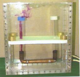
Photo showing the tank during a simulation, with dye-colored water flowing out of the left tube.
¡@
Figure 1b.
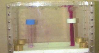
A simulation with strong flow now emerging through the right tube.
¡@
Figure 2.
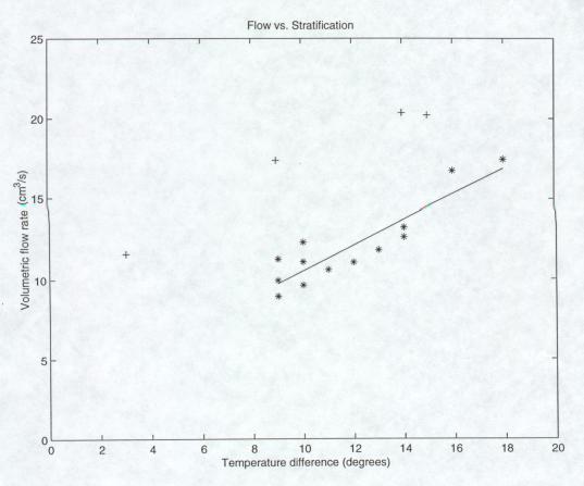
A plot of the volumetric flow rate versus temperature difference beween the lower and upper compartment for 17 consequtive simulations. Except for a set of four outliers (+), the relationship is relatively linear with a correlation coefficient of 0.9.
¡@
Figure 3.
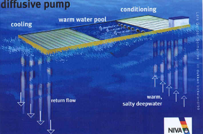
A conceptual sketch of a floating aquaculture installation. Warm deepwater is brought up and guided through the enclosed basin with the fish in the middle, before cooling and downward return.